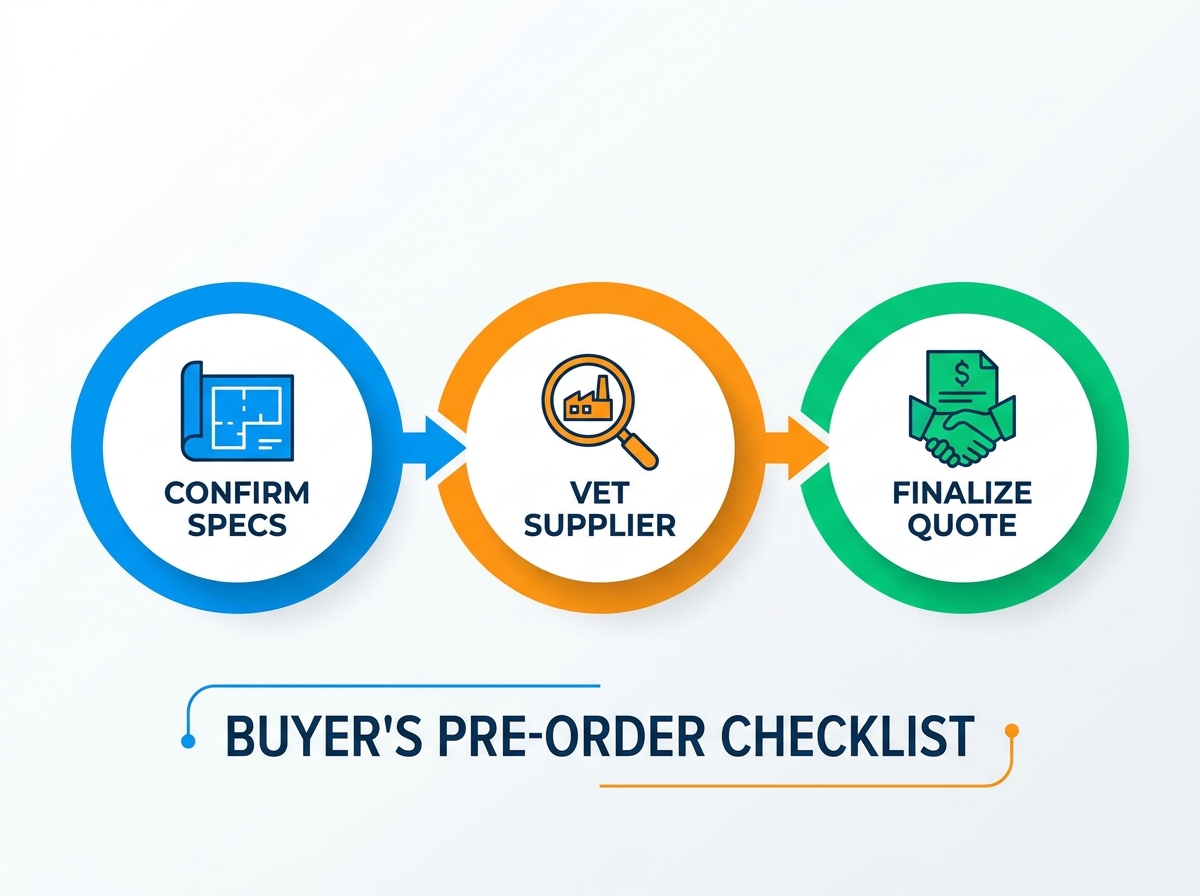
Procuring a large-span roofing or canopy system requires balancing ambitious architectural aesthetics with strict engineering realities. Failures in procurement lead to catastrophic project delays or structural compromises. Buyers often face a disconnect between initial design concepts and the practical limitations of manufacturing, shipping, and assembling complex geometric frameworks. Misjudging load requirements, connection types, or supplier capabilities can inflate budgets by 30% or more. To mitigate risk, procurement teams and lead engineers must follow a rigorous evaluation framework. This guide outlines the exact technical specifications, supplier vetting criteria, and cost-analysis frameworks required to confidently source and order a space frame structure. We detail the intersection of spatial parameters, node selection, and freight logistics so you can ensure structural integrity while maintaining strict control over timelines and material quality.
Clear Use-Case and Spatial Parameters Dictate Engineering: Before finalizing any design, buyers must clearly define the spatial clearance, boundary constraints, and specific application demands of the custom space frame system.
Engineering Alignment is Non-Negotiable: Structural depth, support locations, and load capacities must be finalized before requesting manufacturing bids to avoid costly redesigns.
Node Selection Dictates Assembly: Choosing between a bolted ball space frame and welded nodes directly impacts site installation speed, required labor expertise, and freight logistics.
Supplier Vetting Requires Deep Due Diligence: Evaluating a space frame structure supplier demands strict scrutiny of their in-house non-destructive testing (NDT) capabilities, software proficiency, and raw material sourcing.
Quotes Must Be Deconstructed: A reliable space frame project quote must transparently separate manufacturing costs from freight, anti-corrosion treatments, and on-site technical supervision.
Defining Project Success Criteria and Structural Constraints
Clarifying Intended Application, Spatial Boundaries, and Clearances
The end-use of a facility dictates specific design codes, ventilation requirements, and fire protection standards. A bulk coal storage dome faces highly corrosive internal environments and requires massive clear spans to accommodate heavy stacker-reclaimer machinery. You must account for explosive dust environments and specify appropriate steel grades and coatings. Conversely, an aircraft hangar demands strict adherence to clear height clearances to ensure tail fin passage without obstruction. Commercial canopies and sports stadiums prioritize aesthetic appeal and complex cladding integration. This requires precise coordination between the structural grid and the architectural envelope.
Establishing critical spatial boundaries is the first step in structural planning. Engineers must define exact clear height clearances, maximum allowable column footprints, and physical boundary setbacks imposed by local zoning laws. These dimensions directly influence the geometric layout of the grid. Analyzing how the required spatial envelope limits or enables specific structural configurations is mandatory. A flat grid might suffice for a standard industrial roof. A barrel vault or double-curved dome provides superior wind deflection and aesthetic grandeur for public venues. Each configuration carries distinct implications for steel tonnage and node complexity.
When defining spatial boundaries, field teams should verify the following parameters:
Maximum allowable structural depth based on local height restrictions.
Required clear span dimensions without interior column interference.
Exact locations of existing foundation piles or perimeter support walls.
Clearance requirements for overhead cranes or suspended MEP systems.
Span, Load Capacity, and Structural Depth Ratios
The mathematical relationship between the clear span and the required structural depth determines the overall stiffness of the roof. Calculating dead loads forms the baseline of the structural analysis. This includes the weight of the steel members, cladding materials, and suspended mechanical, electrical, and plumbing systems. Live loads encompass snow accumulation, wind pressure, and seismic activity. You must calculate these based on stringent regional building codes.
Specifying the optimal structural depth involves significant engineering trade-offs. A deeper frame provides a stiffer structure. This allows for lighter individual tubular members and a reduction in total steel weight. However, it consumes more vertical space. A shallower frame preserves vertical clearance but requires heavier members to resist bending moments. This increases overall steel consumption and elevates the risk of localized deflection under heavy snow or wind loads.
Structural Configuration
Typical Depth-to-Span Ratio
Primary Application
Deflection Risk Profile
Flat Grid (Two-Way)
1/10 to 1/15
Industrial roofs, commercial canopies
Moderate (requires cambering for large spans)
Barrel Vault
1/15 to 1/20
Sports facilities, train stations
Low (arch action transfers loads efficiently)
Spherical Dome
1/20 to 1/30
Bulk storage, exhibition halls
Very Low (optimal geometric load distribution)
Support Locations and Moment Contours
The placement of columns or perimeter supports fundamentally alters the degree of structural optimization achievable within the grid. Perimeter supports distribute loads evenly across the boundary. Interior columns introduce concentrated stress points that require reinforced node connections and thicker adjacent members. The plan projection of moment contours dictates the overall weight, distribution, and cost of the steel required. By analyzing these contours, engineers identify zones of maximum stress and optimize member sizing accordingly. This avoids unnecessary material usage in low-stress areas.
Aligning architectural support constraints with engineering safety margins prevents localized overstressing. You must verify column spacing against the natural module size of the grid. Ensure support nodes can accommodate multi-directional shear forces. Confirm that foundation designs can handle the horizontal thrust generated by vaulted or domed configurations. Failure to coordinate support locations early in the design phase inevitably leads to awkward structural modifications and compromised load paths on the job site.
Evaluating Custom Space Frame System Components and Aesthetics
Node Connection Types: Bolted Ball Space Frame vs. Welded Spherical Nodes
The mechanical differences between node types dictate the entire assembly methodology. A bolted ball space frame utilizes solid steel spheres with threaded holes. These connect to tubular members via high-strength bolts and sleeve assemblies. This system offers immense advantages in rapid on-site assembly. It drastically lowers field-welding requirements and mitigates the risks associated with poor weather conditions during installation. The modular nature of bolted balls facilitates highly efficient packing and shipping. This makes it ideal for remote project sites where heavy machinery access is limited.
Welded hollow spherical nodes are manufactured by pressing steel plates into hemispheres and welding them together. These nodes are typically reserved for ultra-heavy-load scenarios. You will see them in massive industrial spans or structures subjected to extreme dynamic forces. Welded systems require highly certified on-site welders. They demand rigorous ultrasonic testing of every field weld and significantly more time for erection. The choice between these two systems fundamentally shapes the project labor requirements and timeline.
Aesthetic Design Integration and Cladding Compatibility
The aesthetic versatility of exposed structural grids allows architects to turn functional roofing into visual centerpieces. Specific node geometries and member arrangements enhance the architectural vision, creating intricate patterns of light and shadow. Integrating a custom space frame system with the building envelope requires meticulous detailing. Different cladding systems demand distinct attachment methods and tolerance accommodations. Insulated glass panels require rigid support to prevent cracking. Multiwall polycarbonate offers more flexibility. Standing seam metal roofs need sliding clips to accommodate thermal expansion.
Establishing structural solutions for secondary bending stresses is critical when attaching cladding. Purlin connection points must be coordinated directly onto the node centers. This ensures loads transfer axially through the members, rather than inducing bending moments along the mid-span of the tubes. Custom support brackets are engineered to bridge the gap between the primary grid nodes and the secondary cladding rails. This guarantees a watertight and structurally sound envelope.
Material Grades and Anti-Corrosion Treatments
Standard steel grades used in these structures typically include Q235B and Q355B. These align with international equivalents like S275 and S355. The selection of steel grade depends on the required yield strength and the specific load demands of the project. High-stress zones utilize Q355B for its superior load-bearing capacity. Standard members rely on Q235B to optimize material efficiency without sacrificing safety.
Anti-corrosion treatments dictate the lifecycle longevity of the structure. Hot-dip galvanizing provides robust, long-lasting protection by metallurgically bonding zinc to the steel. This makes it highly suitable for harsh environments. A system of epoxy zinc-rich primer followed by polyurethane topcoats offers excellent corrosion resistance combined with customizable color options for exposed architectural applications. Environmental factors dictate the required micron thickness of these protective coatings.
Coating System
Typical Thickness (Microns)
Best Application Environment
Field Touch-Up Difficulty
Hot-Dip Galvanizing
85 - 120
Coastal, high-humidity, industrial
High (requires specialized zinc-rich cold galvanizing spray)
Epoxy Primer + Polyurethane Topcoat
150 - 250
Commercial, architectural exposed steel
Low (standard brush or spray application)
Fluorocarbon Paint (PVDF)
200 - 300
High UV exposure, premium architectural
Moderate (requires precise surface preparation)
Vetting a Space Frame Structure Supplier
Manufacturing Capacity and Quality Control (QA/QC)
Evaluating a space frame structure supplier begins with verifying their mandatory factory certifications. ISO 9001 ensures standardized management processes. EN 1090 or AISC certifications validate the facility capability to produce structural steel to stringent international codes. Buyers must request specific QA/QC documents. You need mill test certificates for all raw steel batches. You need dimensional inspection reports for fabricated members. You must demand third-party non-destructive testing (NDT) reports for both factory and field welds.
Factory pre-assembly testing is a non-negotiable step for projects featuring complex, non-standard geometries. Reputable suppliers physically assemble critical sections of the grid within their facility. This verifies tight tolerances and ensures all nodes and members align perfectly before shipping. This preemptive quality check eliminates the risk of discovering dimensional discrepancies once the materials reach the construction site. Field modifications are exponentially more difficult and costly.
Assessing a Space Frame Manufacturer in China
Sourcing from global manufacturing hubs offers significant economic advantages and access to massive production capacities. Navigating the logistical realities requires a structured vetting framework. When evaluating a space frame manufacturer China, buyers must verify export licenses. Review international project portfolios to confirm the supplier experience with cross-border logistics and foreign building codes. Hiring third-party quality inspectors, such as SGS or TUV, to conduct pre-shipment inspections ensures the final product matches the approved shop drawings.
Communication protocols are equally critical. The supplier must demonstrate the ability to produce comprehensive, bilingual engineering drawings and installation manuals. Misinterpretations of technical specifications due to language barriers lead to severe fabrication errors. Establishing clear, documented communication channels and requiring English-language technical documentation safeguards the procurement process.
Engineering and Design Software Capabilities
The structural integrity of a complex grid relies heavily on the precision of the initial detailing. The supplier must be highly proficient in advanced structural detailing software. SFCAD, Tekla Structures, and SAP2000 are industry standards. These platforms allow engineers to perform rigorous finite element analysis. They simulate load distributions and generate precise fabrication data for CNC machinery.
Comprehensive shop drawings are the lifeblood of the fabrication process. The supplier must provide detailed node-numbering diagrams, precise member lengths, and clear installation sequences. These documents translate the theoretical engineering model into actionable instructions for the factory floor and the on-site assembly crew. They ensure every component fits exactly as intended.
Deconstructing a Space Frame Project Quote
Identifying Hidden Costs in Logistics and Freight
A reliable space frame project quote must transparently separate manufacturing costs from logistics. The volumetric weight of the structural components heavily impacts shipping container optimization. Tubular members can be bundled efficiently. Large welded nodes or pre-assembled modules consume significant space. They potentially require open-top containers or flat racks, which carry higher freight rates. Understanding these volumetric constraints is essential for accurate freight budgeting.
INCOTERMS dictate how risk and costs are distributed between the buyer and the supplier. Buyers must clearly understand who is responsible for customs clearance, import tariffs, and inland freight to the final job site. Packaging protocols must be scrutinized. Improperly packed steel members rub against each other during maritime transit. This damages anti-corrosive coatings and requires expensive on-site touch-ups before installation.
Installation Support vs. Turnkey Delivery
Quotes vary wildly depending on the scope of on-site services provided. Some quotes only cover material supply. This leaves the buyer responsible for hiring local erection crews and managing the installation process. Others include on-site technical supervision, where the manufacturer sends experienced engineers to guide the local labor force. Full turnkey delivery encompasses material supply, logistics, and complete installation by specialized teams.
Buyers must identify the hidden costs associated with installation. Renting specialized lifting equipment represents a massive expense. Heavy-duty cranes and extensive scaffolding systems are mandatory for large spans. If these equipment costs are not explicitly covered in the turnkey contract, the buyer must budget for them separately. Clarifying the exact boundaries of supplier responsibility prevents sudden budget overruns during the erection phase.
Implementation Risks and Mitigation Strategies
Site Assembly Challenges and Tolerances
Assembling hundreds of nodes and members introduces the risk of cumulative tolerance errors. A fraction of a millimeter deviation at a single node multiplies across a large span. This results in significant misalignment at the perimeter supports. Strict adherence to the supplier numbering sequence is mandatory. Components are fabricated for specific locations within the grid. Mixing them up compromises the entire structural geometry.
Mitigation strategies include implementing sequential tightening protocols. Bolts should be initially hand-tightened to allow for slight adjustments as the grid takes shape. Follow this with a final torqueing sequence once the entire section is aligned. Surveying support points with total stations before assembly begins ensures the foundation matches the theoretical model. This provides a highly accurate baseline for the erection process.
Long-Term Maintenance and Inspection Protocols
Post-installation maintenance is a reality for all large-span structures. Bolted connections are subjected to continuous thermal expansion and contraction. This causes bolts to loosen over time. Establishing a standard inspection schedule is critical for long-term safety. Maintenance teams must periodically check bolt torque levels. This is especially important after extreme weather events or seismic activity.
Inspecting coating integrity is equally important. Scratches or localized degradation of the anti-corrosion treatment must be repaired immediately. This prevents rust from compromising the steel members. Routine visual inspections should look for signs of localized deflection or unexpected stress patterns in the cladding. These indicate underlying structural shifts.
Conclusion
Draft a comprehensive Request for Quotation (RFQ) that includes architectural plans, local load requirements, and specific anti-corrosion standards.
Require all bidding suppliers to submit verifiable NDT reports and sample bilingual shop drawings with their proposals.
Hire a third-party inspection agency to conduct a factory audit before signing the final procurement contract.
Establish a clear matrix for freight responsibilities, explicitly defining INCOTERMS and container packing protocols.
FAQ
Q: What information is required to get an accurate space frame project quote?
A: Buyers must provide detailed architectural drawings, exact clear span dimensions, and local building code requirements for wind, snow, and seismic loads. Specifying boundary constraints, preferred node types, and the intended cladding system allows the manufacturer to calculate precise steel tonnage and engineering requirements.
Q: What is the difference between a bolted ball space frame and a welded system?
A: A bolted system uses threaded solid spheres and high-strength bolts, allowing for rapid on-site assembly and eliminating field welding. Welded systems use hollow spherical nodes welded directly to the members on-site, offering higher load-bearing capacities but requiring highly skilled labor, extensive testing, and longer installation times.
Q: How do I safely evaluate a space frame manufacturer in China?
A: Safe evaluation requires verifying international certifications like EN 1090 or AISC and reviewing documented past export projects. Hire third-party auditing firms like SGS or TUV to conduct factory inspections, verify raw material mill certificates, and perform pre-shipment quality checks.
Q: How long does it take to manufacture and deliver a custom space frame system?
A: Timelines vary based on complexity. They typically require 2 to 4 weeks for shop drawing approval, 4 to 8 weeks for fabrication and factory testing, and 3 to 6 weeks for ocean freight and customs clearance. Buyers should plan for a total lead time of 3 to 5 months.
Q: What is the maximum span of a space frame structure without interior columns?
A: Standard engineering limits allow these structures to easily span from 30 meters to over 100 meters without interior supports. The maximum achievable span depends heavily on the structural depth ratio, the thickness of the steel members, and the specific geometric configuration.
Q: How are space frames shipped internationally?
A: Components are disassembled to optimize volumetric weight. Tubular members are bundled tightly. Nodes and bolts are packed in reinforced wooden crates. These materials are loaded into standard 20ft or 40ft shipping containers, ensuring anti-corrosion coatings are protected with proper dunnage during maritime transit.
A comprehensive steel structure company integrating processing design, installation, and technical services.
About Lianfang
Is a comprehensive steel structure company integrating processing design, installation and technical services of grids, steel structures, pipe trusses and spherical grids.